You are using an out of date browser. It may not display this or other websites correctly.
You should upgrade or use an alternative browser.
You should upgrade or use an alternative browser.
40HP Avery Phase III
- Thread starter 40avery
- Start date

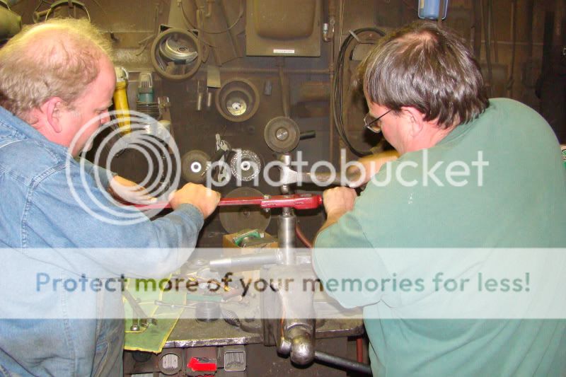
Pete and I mount up the shifter linkage for the clutch/two speed drive.
Differential has been rebuilt and mounted up.
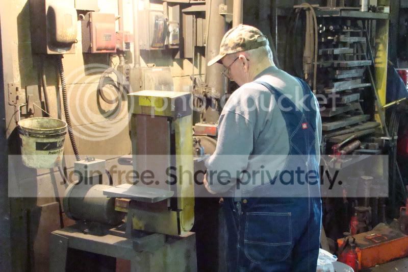
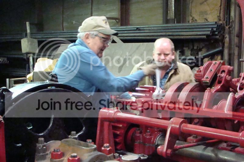
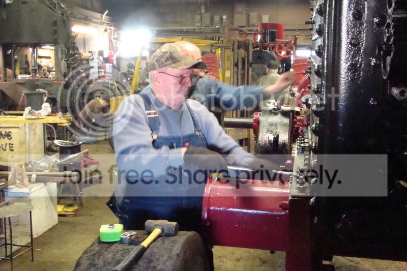
Bud buffs up some parts for the mount up.
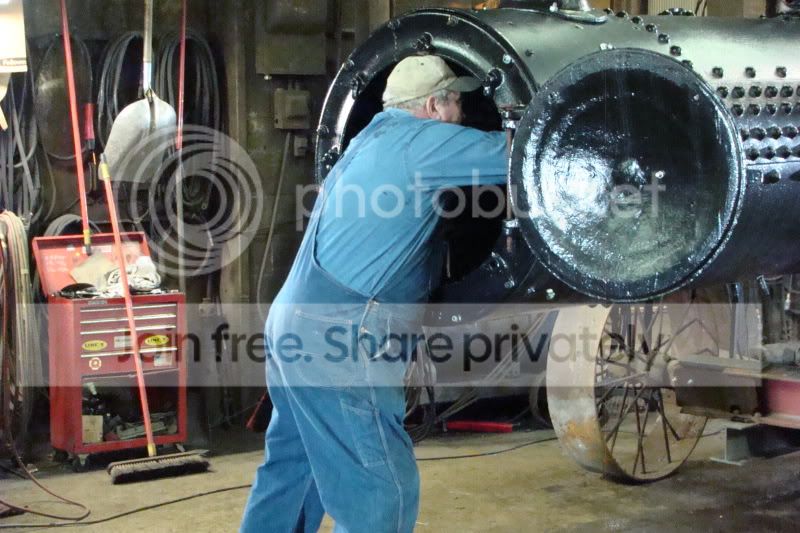
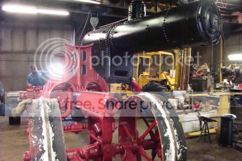
Boiler is ready for mounting and pushed off tot he side to get the running gear in place
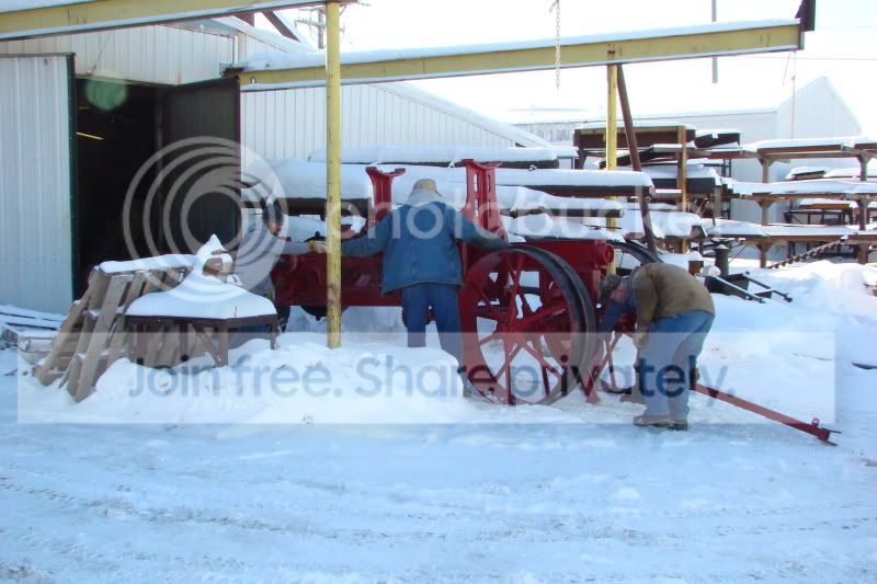
Running gear comes out of the lean to.
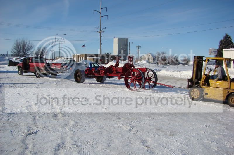
Steel Wheels on really cold snow moves hard. Mark had to assist the forklift!
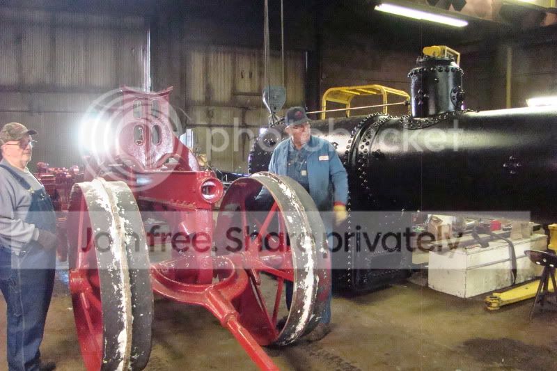
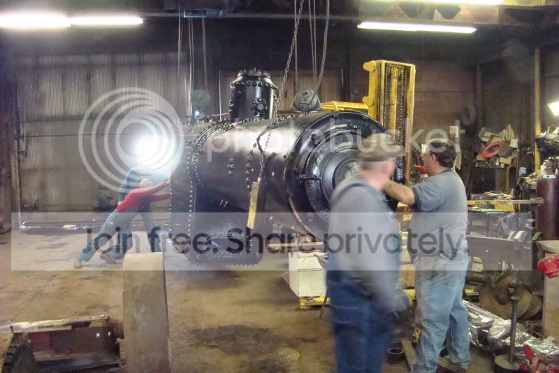
In the shop and getting the spot right for the mount up.
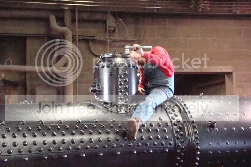
Boiler had to be re rigged a bit. Kelly being the smaller in stature usually gets the firebox duty.
Going up.
and up
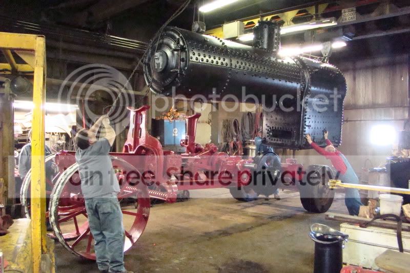
and over
And down
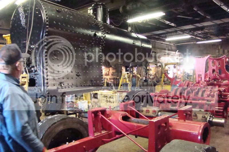
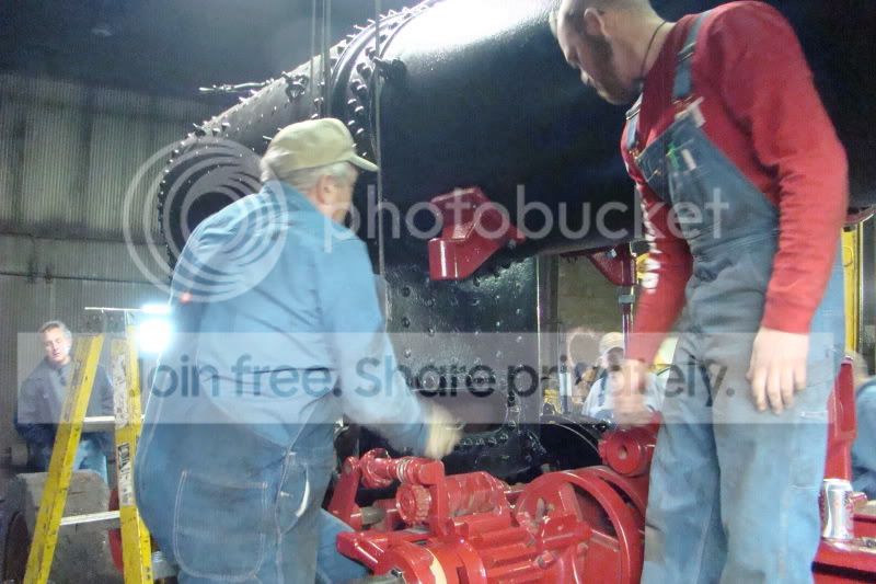
In line - Ready for final adjustments
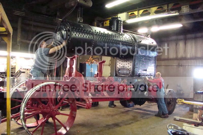
Mounting holes in line and ready to settle in.
Front end lined up and ready to set in.
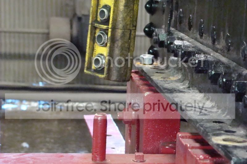
First bolt in.
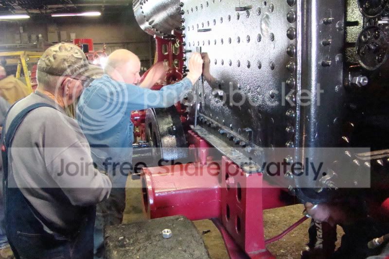
Line up punches in and boiler is being secured.

Mark K. using the force to torque up the mounting bolts.
Thanks for all the pictures documenting this. It is really looking great. I bet it is a great feeling seeing it come together like that. I am really looking forward to seeing it in person. It is good to see another engine come back to life.
Darren
Darren

I wonder what I was doing with that die grinder up in the air like that? 
This has been a really fun build. I am glad I get to have some part in it, as the 40 I help run (Bridens) went through the same process back in the late 1980's... before my involvement in steam. You hang around these folks, and you learn a lot! Most of the guys you see working on this engine throughout the 3 threads on the build have been there since it was nothing but a big parts pile!
Keep up the great work on the thread Rick! Thanks!!!
I know these weekends are not "official" donut tasting weekends but there have been a few that have kept up the tradition anyhow!

And Mark couldn't find a Donut but he did find a cookie. I thought he was going to choke on it trying to get it down before I took the picture

And Mark couldn't find a Donut but he did find a cookie. I thought he was going to choke on it trying to get it down before I took the picture
I have it on good authority that this engine came to life again on Sunday February 20, 2011! (on compressed air anyway...) The owner claims it runs PERFECT! As a matter of fact, he CLAIMS it runs better than Jim's!
I wish I could have been there to see it, and I sure hope someone there got some video (Louie???)
Pete Mandt worked long and hard on the timing. I have been told that Jim's 40 has some kind of timing issue, so guess who we are going to recruit to check it out on (if not before) steam school weekend!
Congratulations to Mark Pedersen and all who are involved in this project! It is getting close to being finished!
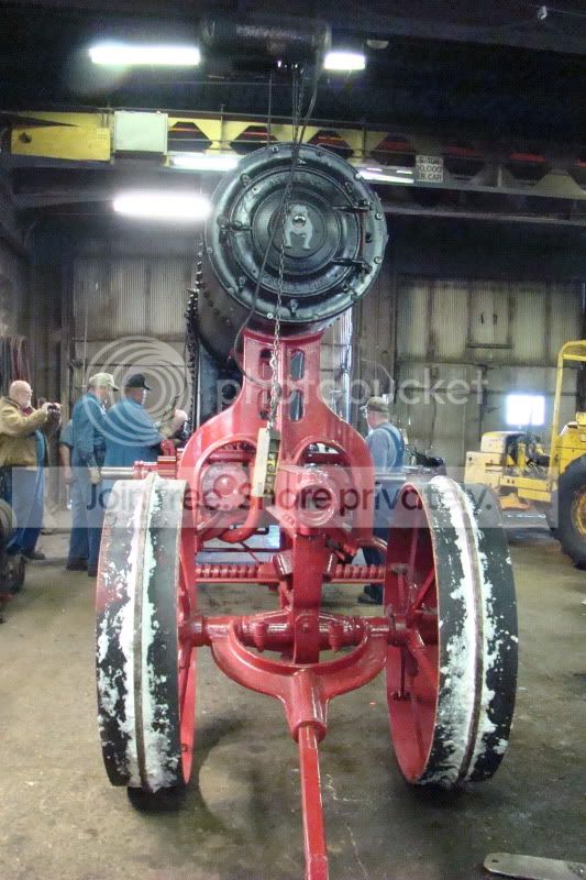
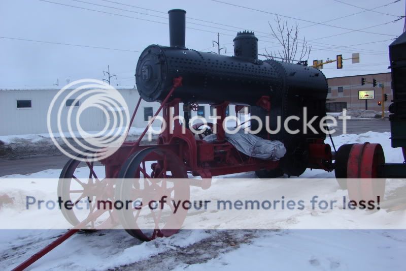
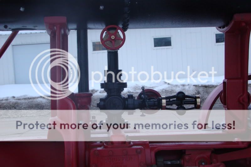
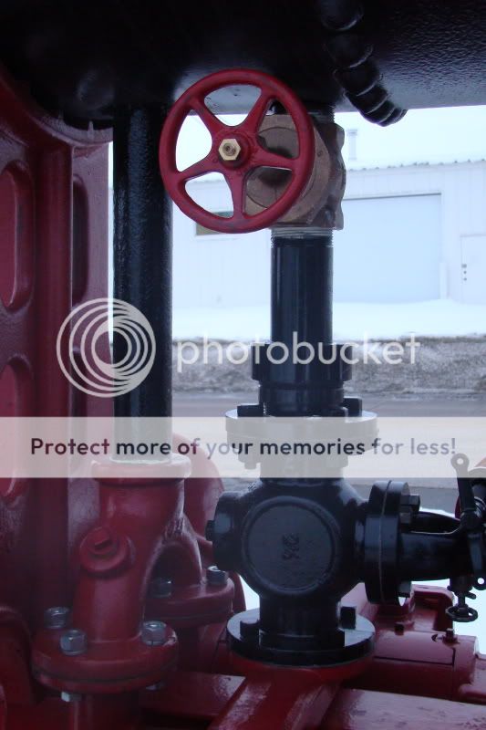
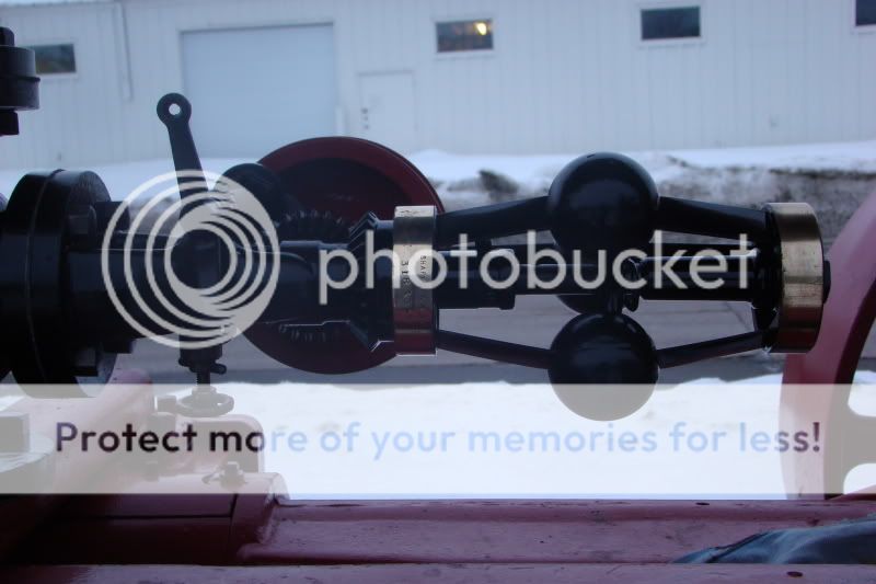
Here are a few pictures I took of the engine a few weeks back when it was sitting outside Jim's shop.
I wish I could have been there to see it, and I sure hope someone there got some video (Louie???)
Pete Mandt worked long and hard on the timing. I have been told that Jim's 40 has some kind of timing issue, so guess who we are going to recruit to check it out on (if not before) steam school weekend!
Congratulations to Mark Pedersen and all who are involved in this project! It is getting close to being finished!
Here are a few pictures I took of the engine a few weeks back when it was sitting outside Jim's shop.
Mark,
I will have to check my schedule before I help with any tuneup. I may not be able to fit one in until we have a chance to see which 40 Avery is the BIG 40 AVERY.
May the best Bulldog win!
Pete
I will have to check my schedule before I help with any tuneup. I may not be able to fit one in until we have a chance to see which 40 Avery is the BIG 40 AVERY.
May the best Bulldog win!
Pete
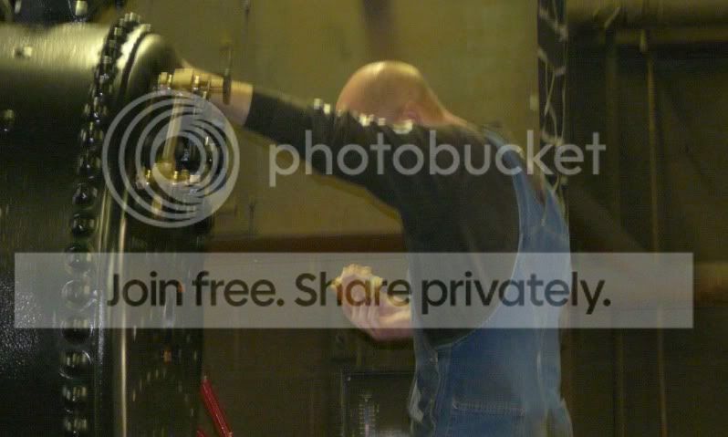
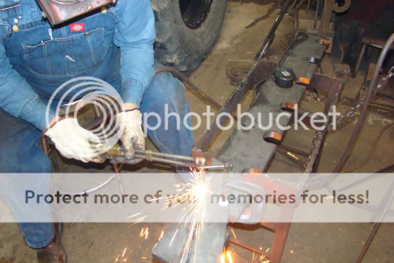
Some photos from Saturday re-riveting the eccentric strap / valve linkage. Can't remember for sure why they had to be re-riveted... 
Heating...
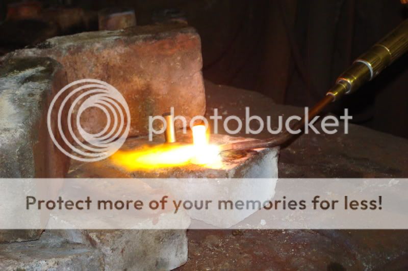
Delivery...

Quick Mark...

Finishing up...
Heating...
Delivery...
Quick Mark...
Finishing up...
Rick H, Kelly M, Katy and I got pressed into service this past weekend to make grate hangers, prep and install the grates in the 40 while Mark P was way up in Canada playing!
Mark decided to go with the "Field tested" grates that we have in Jim's 40! No sense messing with something that works... at least not for now! These same grates have also found there way into a lot of 80 Case boilers.
Rick and I built the set that are in Jim's 40 quite a few years ago, so this was round 2 for us! It was fun to build another set with him... this time we had something to copy!
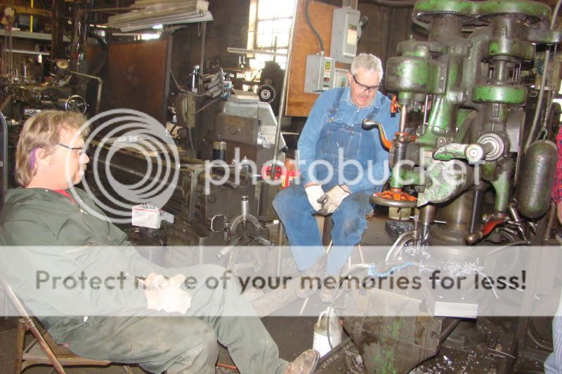
It the first two photos, Katy and Ted Mandt take turns cleaning up the holes, all 966 of them!!! in the 7 grates. The holes are cast to end up 1/2", but the process leaves behind a lot of undesirable material so they are drilled out to 9/16 to clean them up and make a smooth surface for the air to travel through.


The holes in the grates are cone shaped, so the air is actually accelerated as it us drawn through the grates with the draft. Ingenious design, and very effective!
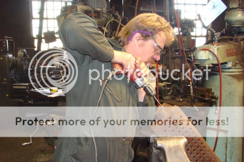
Rick and I teamed up laying out and drilling the holes in the grate hangers. We started with 1/2" holes, then 1", and I think we ended up with something around 2-1/2" holes. The two hangers were welded together so we only had to lay it out and drill it once.
In this picture it looks like we are at the 1" step. We really were busy... we just got to sit for about 3 minutes while the drill press auto fed through the 2" thick material (2-1" pieces) and then we would have to re-set the work and drill the next hole.
After the holes were drilled we cut out the tops of the holes with the band saw to form the "U" shaped cradle for the grates to set in. I then cut the two pieces apart and in the picture below Rick cuts the final shape into each hanger.
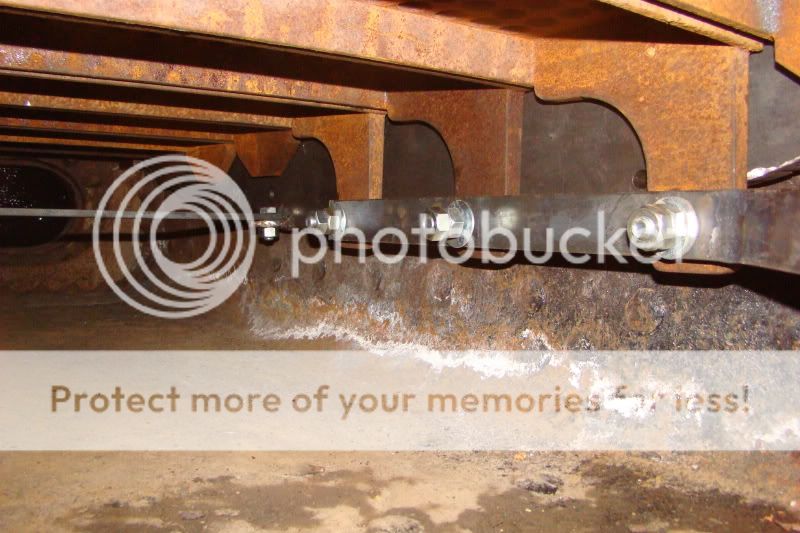
While Rick was doing that, Kelly M (not pictured, sorry Kelly) were drilling holes in the rocker arms in the 7 grates. While only 3 of them will be hooked up to rock, 3 more of them will be bolted solid with these arms to keep them level.
A finished grate hanger bracket ready to go into the boiler!
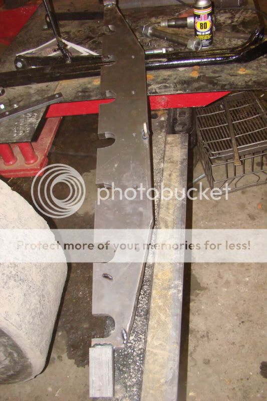
The 4" long pieces welded to each end are by design. The hanger supports are narrower than the firebox to miss the rivets in the corners, but the hangers have to be closer to the outsides of the firebox to make room for the grates. The design is very similar, and were patterned after the original grate hangers.
Mark decided to go with the "Field tested" grates that we have in Jim's 40! No sense messing with something that works... at least not for now! These same grates have also found there way into a lot of 80 Case boilers.
Rick and I built the set that are in Jim's 40 quite a few years ago, so this was round 2 for us! It was fun to build another set with him... this time we had something to copy!
It the first two photos, Katy and Ted Mandt take turns cleaning up the holes, all 966 of them!!! in the 7 grates. The holes are cast to end up 1/2", but the process leaves behind a lot of undesirable material so they are drilled out to 9/16 to clean them up and make a smooth surface for the air to travel through.
The holes in the grates are cone shaped, so the air is actually accelerated as it us drawn through the grates with the draft. Ingenious design, and very effective!
Rick and I teamed up laying out and drilling the holes in the grate hangers. We started with 1/2" holes, then 1", and I think we ended up with something around 2-1/2" holes. The two hangers were welded together so we only had to lay it out and drill it once.
In this picture it looks like we are at the 1" step. We really were busy... we just got to sit for about 3 minutes while the drill press auto fed through the 2" thick material (2-1" pieces) and then we would have to re-set the work and drill the next hole.
After the holes were drilled we cut out the tops of the holes with the band saw to form the "U" shaped cradle for the grates to set in. I then cut the two pieces apart and in the picture below Rick cuts the final shape into each hanger.
While Rick was doing that, Kelly M (not pictured, sorry Kelly) were drilling holes in the rocker arms in the 7 grates. While only 3 of them will be hooked up to rock, 3 more of them will be bolted solid with these arms to keep them level.
A finished grate hanger bracket ready to go into the boiler!
The 4" long pieces welded to each end are by design. The hanger supports are narrower than the firebox to miss the rivets in the corners, but the hangers have to be closer to the outsides of the firebox to make room for the grates. The design is very similar, and were patterned after the original grate hangers.
The grates are all installed in the boiler!
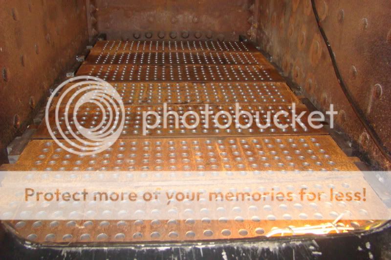
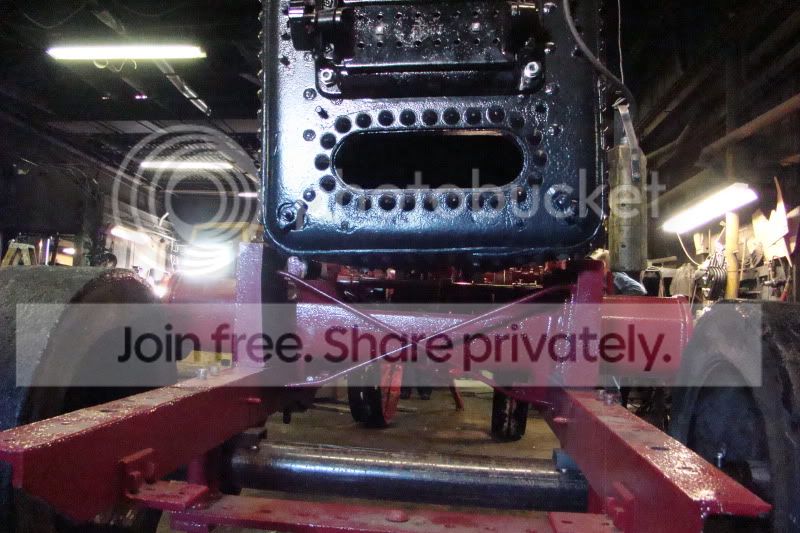
A look underneath through the rear draft door.
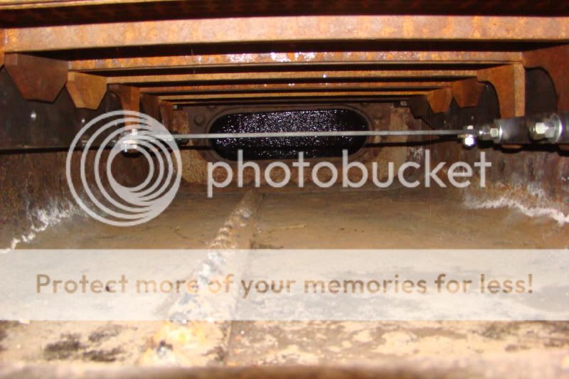
And a close up of the rocking linkage on the 3 grates that will rock. The only time we use the rockers are for cleaning out the firebox before we fire in the morning, or at the end of the season.
Rick and I ran out of time to finish up, but Kelly stayed and built the dead plates for the front and back of the firebox. The front one is something like 10" wide, and the rear about 4". I will get some pictures of all of that next time I am around the engine!
Thanks for taking up the slack Kelly!
A look underneath through the rear draft door.
And a close up of the rocking linkage on the 3 grates that will rock. The only time we use the rockers are for cleaning out the firebox before we fire in the morning, or at the end of the season.
Rick and I ran out of time to finish up, but Kelly stayed and built the dead plates for the front and back of the firebox. The front one is something like 10" wide, and the rear about 4". I will get some pictures of all of that next time I am around the engine!
Thanks for taking up the slack Kelly!
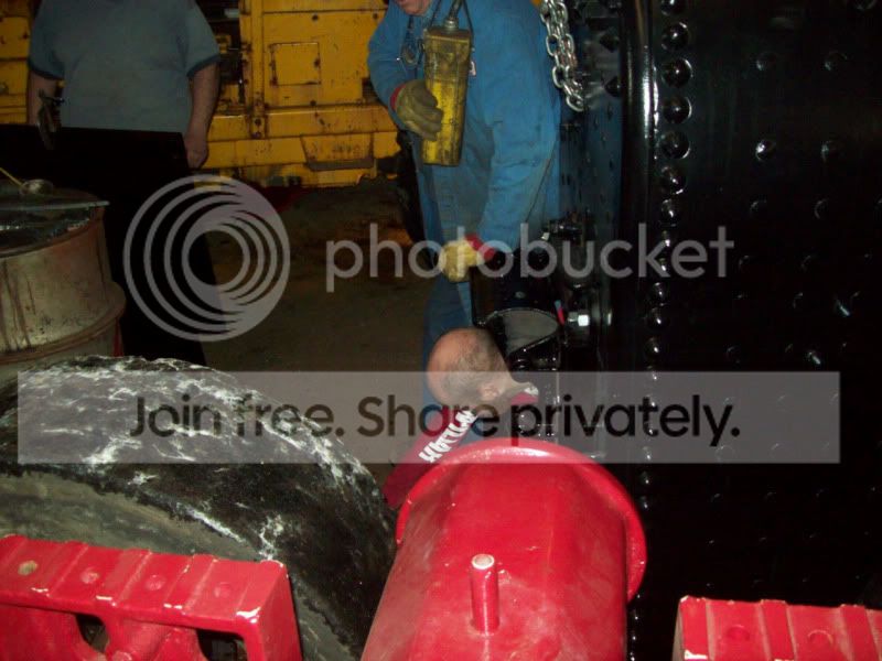
Recently I visited the Henry Ford Museum in Dearborn, Michigan and saw the Avery 30-Horsepower Steam Traction Engine. I am always impressed by the quality of the workmanship that went into the manufacture of the machines of that era.
I did a Google on the 30-hp Avery and your forum came up in the search. I was fascinated by this thread which depicts with photographs much of what you guys went through in rebuilding a 40-hp Avery and I think almost anyone in your group will be able to answer my questions that concern the spring-cushioned drive spokes (rods?) in the drive wheel.
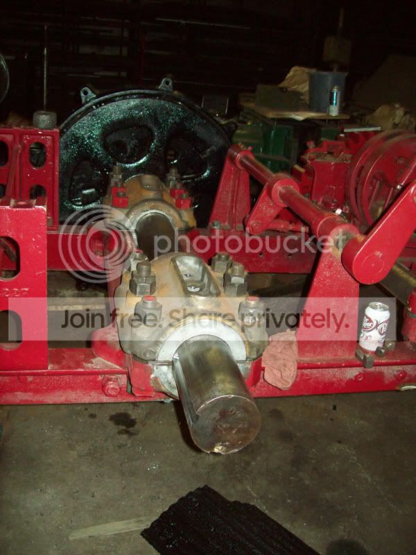
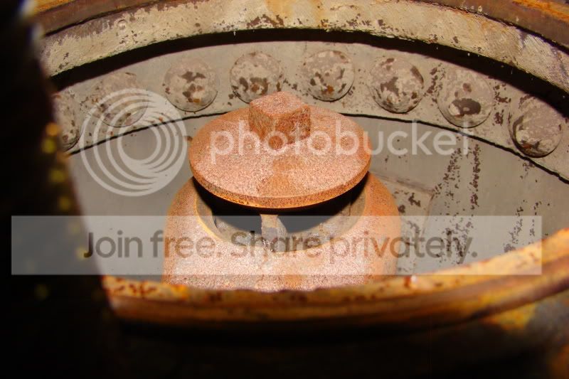
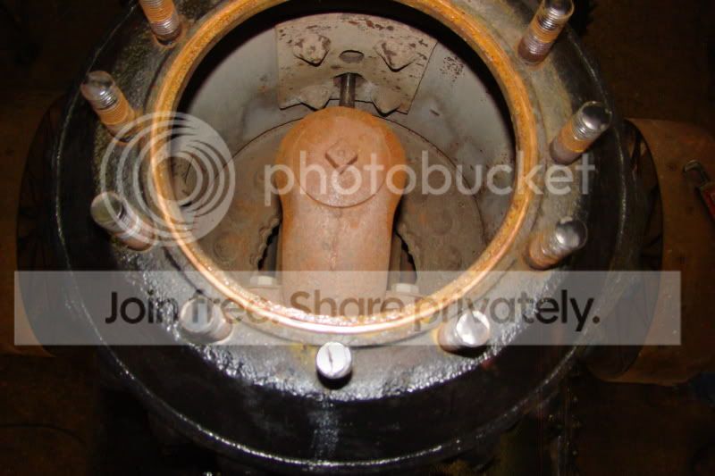
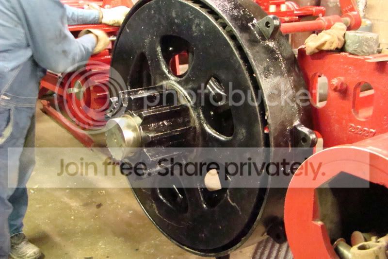
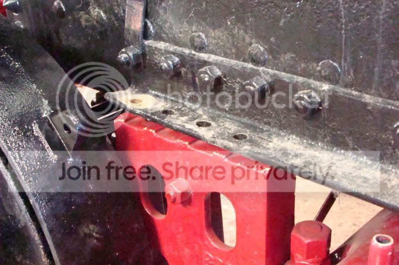
Referencing the photo below -- or attached, am I correct in assuming that a projection such as this, "A", on the bull gear fits into a slot on the drive wheel? (I'm not saying that that particular projection fits into that particular slot.)
I see that the red "bolt", "B", goes through what appears to be an elongated hole in the drive wheel. What keeps these "bolts" in place? A cotter pin? A threaded nut? Approximately how many degrees can the bull gear rotate relative to the drive wheel?
Is this set-up with the springs necessary so that the load is not applied abruptly to the engine when it's put in gear?
Are adjustments made so that each of the five spring-cushioned spokes (rods?) carry about the same load?
Is such cushioning mechanism typical of steam traction engines of that era or is this peculiar to Averys?
While I'm at it, does this machine have a differential? If not, how is turning the tractor handled?
Thank you.
I did a Google on the 30-hp Avery and your forum came up in the search. I was fascinated by this thread which depicts with photographs much of what you guys went through in rebuilding a 40-hp Avery and I think almost anyone in your group will be able to answer my questions that concern the spring-cushioned drive spokes (rods?) in the drive wheel.
Referencing the photo below -- or attached, am I correct in assuming that a projection such as this, "A", on the bull gear fits into a slot on the drive wheel? (I'm not saying that that particular projection fits into that particular slot.)
I see that the red "bolt", "B", goes through what appears to be an elongated hole in the drive wheel. What keeps these "bolts" in place? A cotter pin? A threaded nut? Approximately how many degrees can the bull gear rotate relative to the drive wheel?
Is this set-up with the springs necessary so that the load is not applied abruptly to the engine when it's put in gear?
Are adjustments made so that each of the five spring-cushioned spokes (rods?) carry about the same load?
Is such cushioning mechanism typical of steam traction engines of that era or is this peculiar to Averys?
While I'm at it, does this machine have a differential? If not, how is turning the tractor handled?
Thank you.
The bull gears are free to turn on the hub. The bull gears are attached through the slotted holes you are referring to in the wheel hub. They are attached with bolts that are loose enough to allow the gear to move but they are double nutted so the bolts stay in. The bull gears do transfer power to the ears on you see on the wheels.
The springs are to cushion driving forces. These springs are incorporated in the wheel on this Avery, some other engines have them incoporated in the differential.
Steam traction engines do have a differential to allow for turning.
Hope I got that all correct and that it answers your question.
Pete
The springs are to cushion driving forces. These springs are incorporated in the wheel on this Avery, some other engines have them incoporated in the differential.
Steam traction engines do have a differential to allow for turning.
Hope I got that all correct and that it answers your question.
Pete