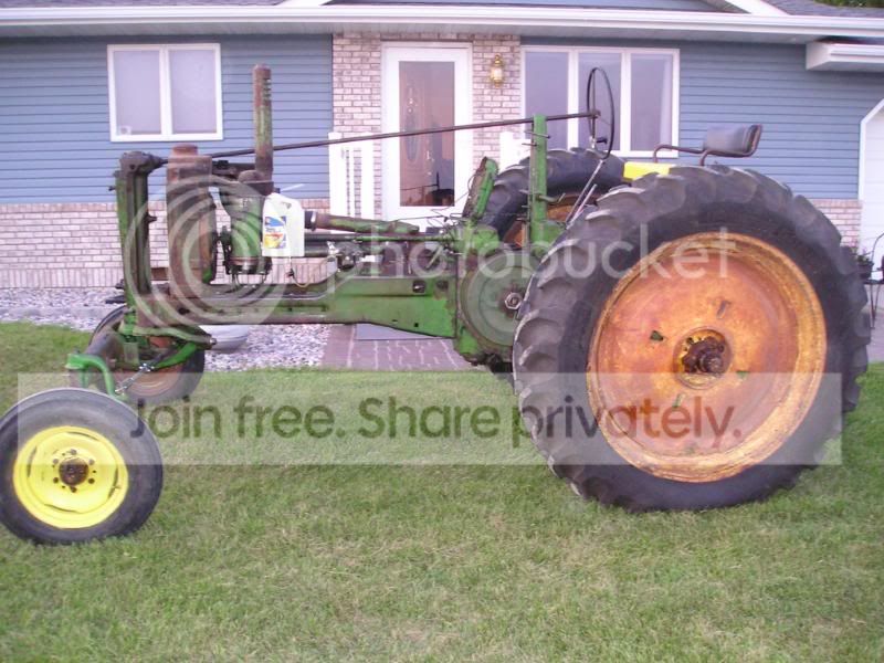
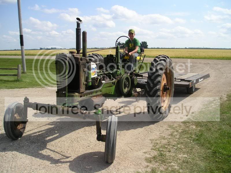
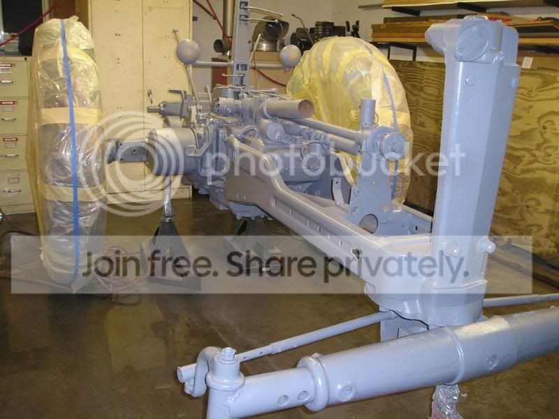
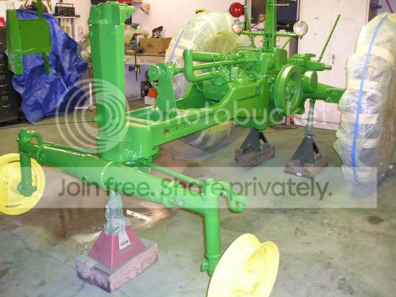
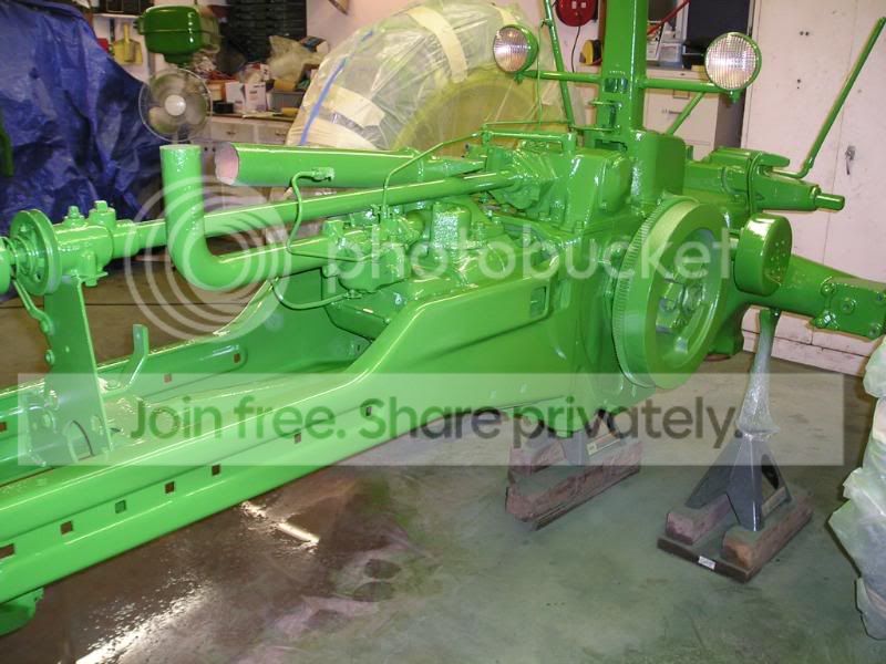
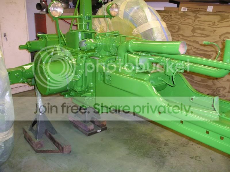
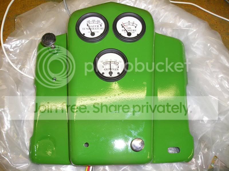
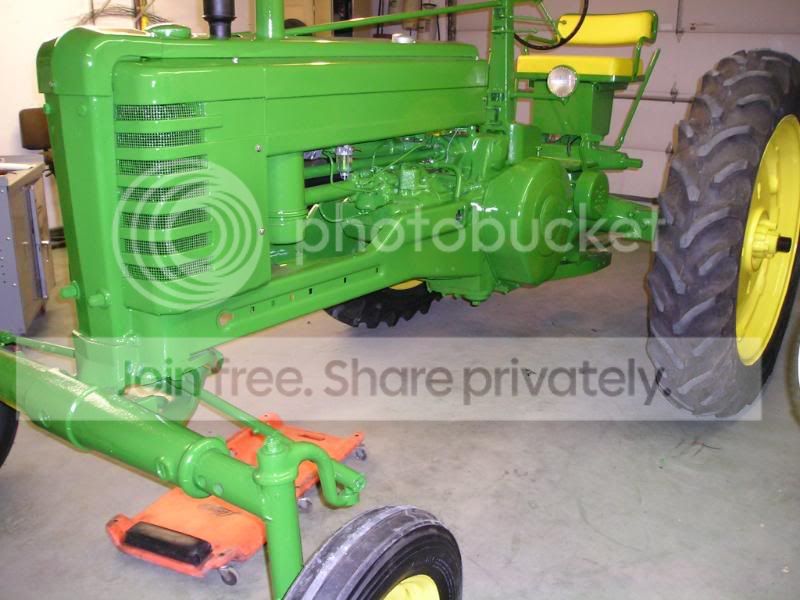
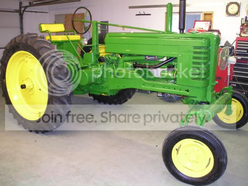
My John Deere model B restoration

My B

P1010070CBsBDisassemblyPowertrolBla.jpg

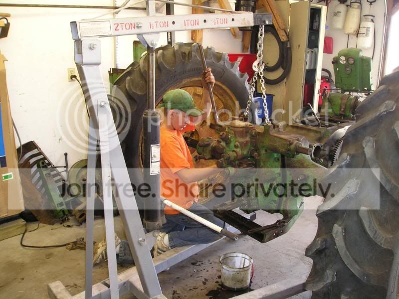
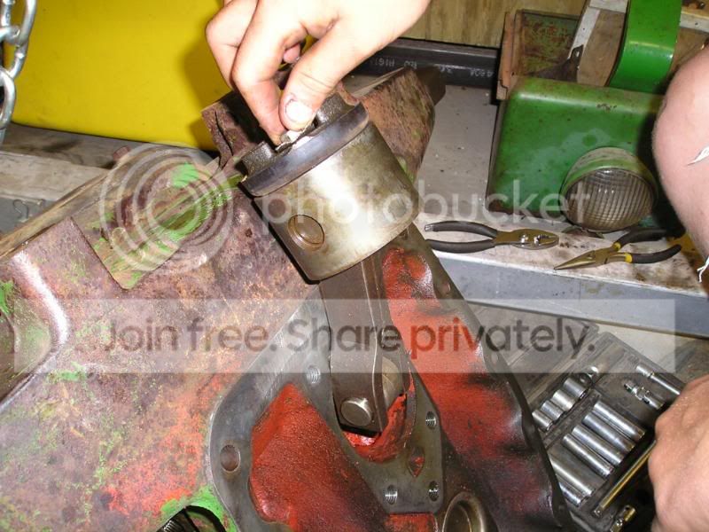
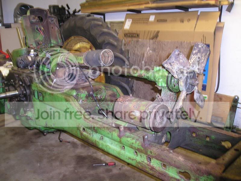
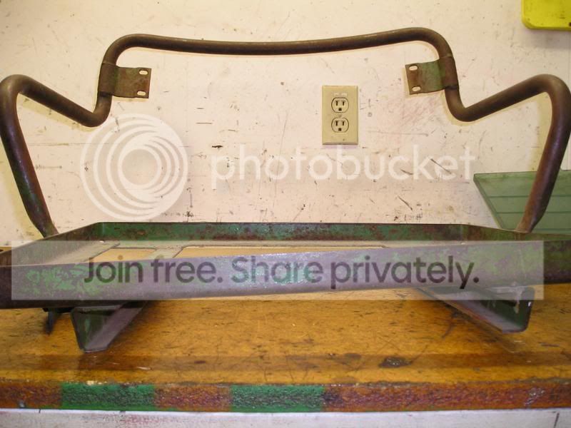
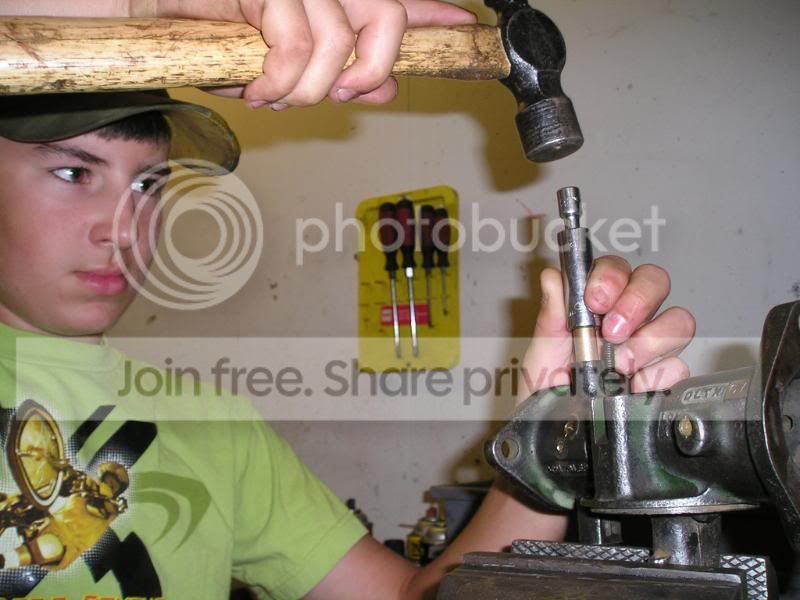
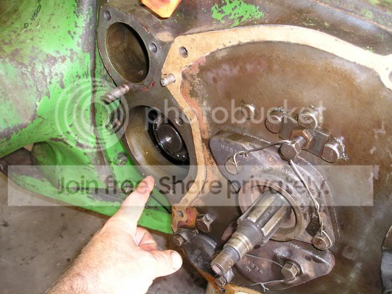
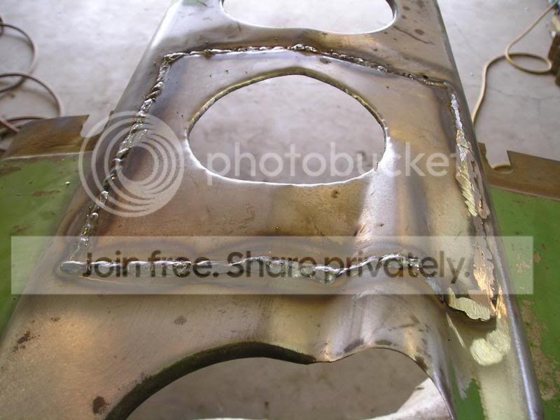
Here we are removing the powertrol and final drive cover.

P1010071CBsBDisassemblyPowertrol.jpg

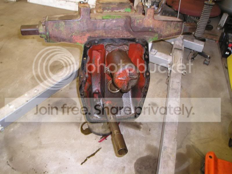
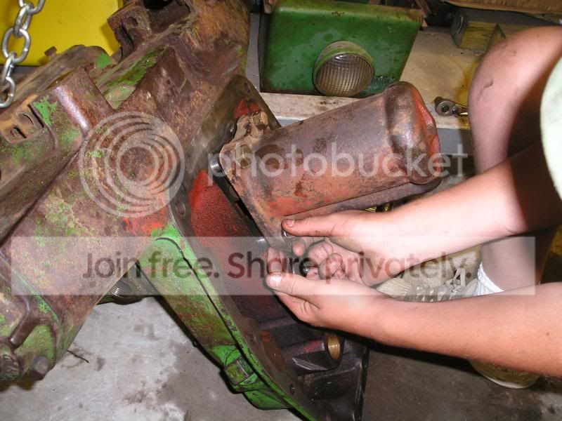
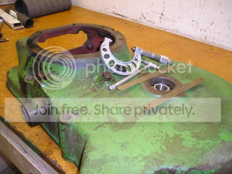
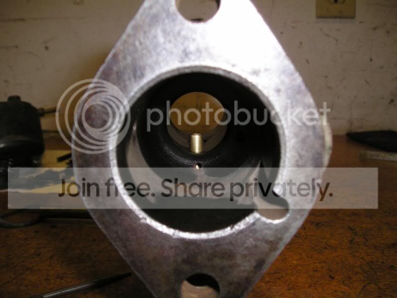
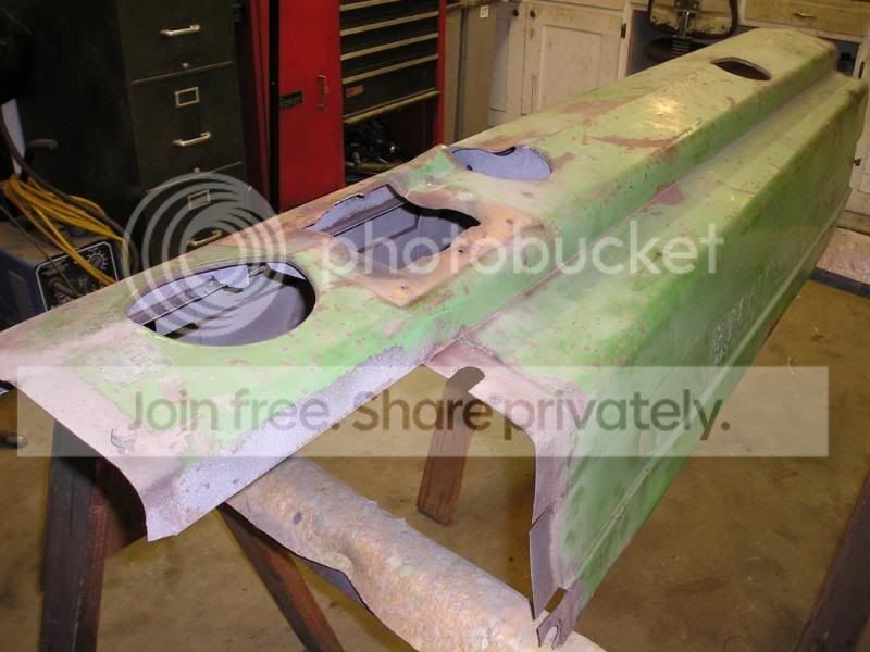
Here is what it looks like from the inside.

P1010073CBsBDisassemblyTransmission.jpg

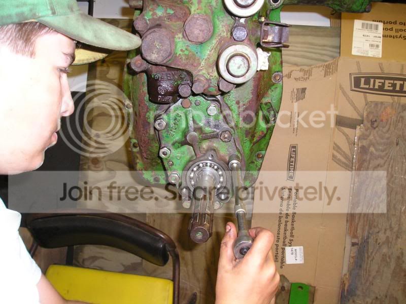
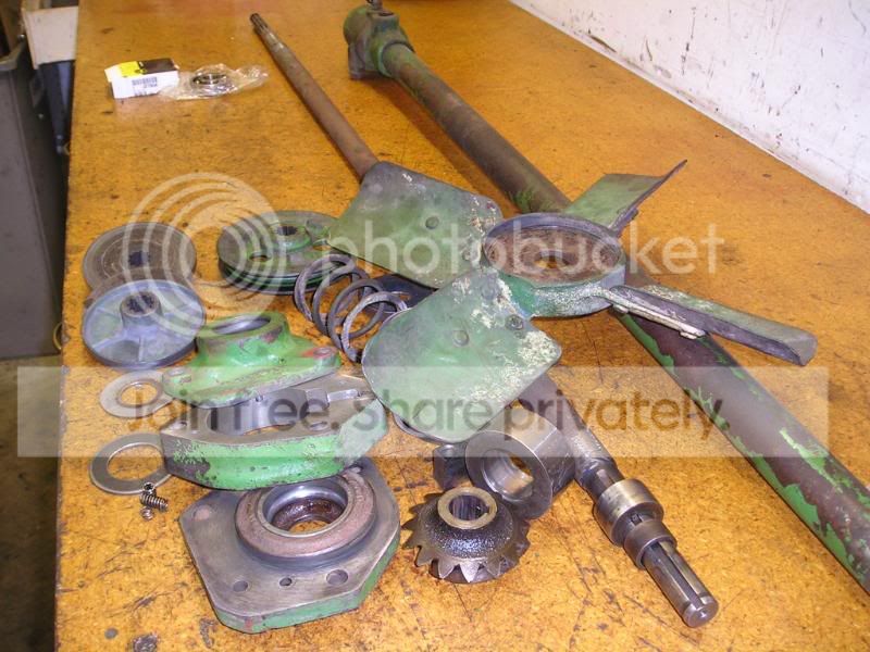
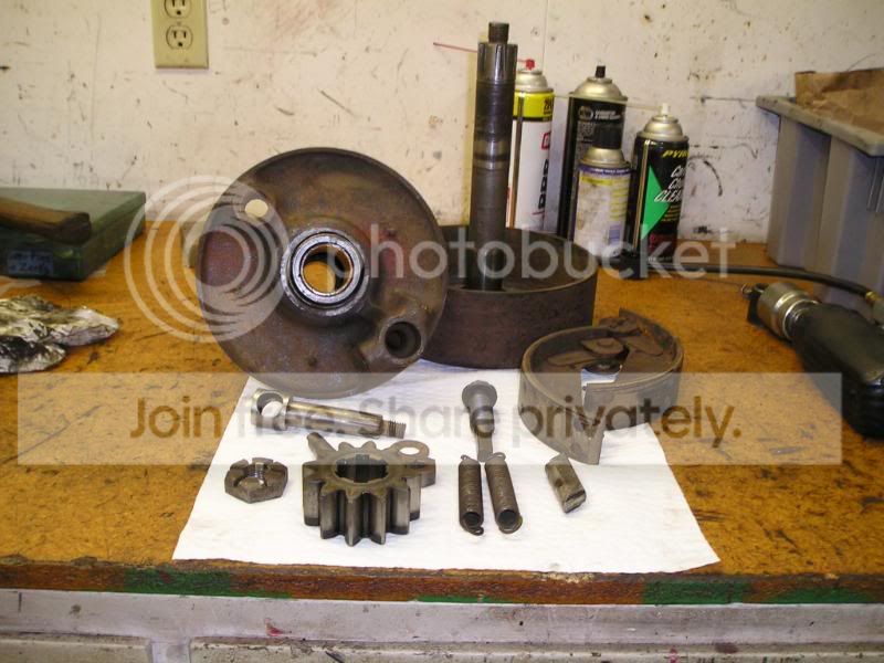
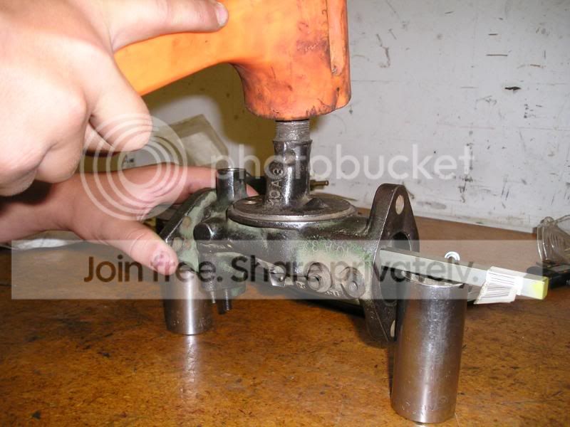
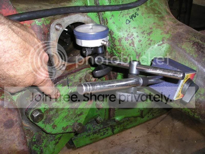
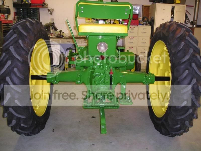
Here is the final drive bull gears on the axles. The differential shaft is just beyond that. Near the bottom you can see the front section of the PTO shaft.

P1010074CBsBAssemblyTransmissionlBl.jpg

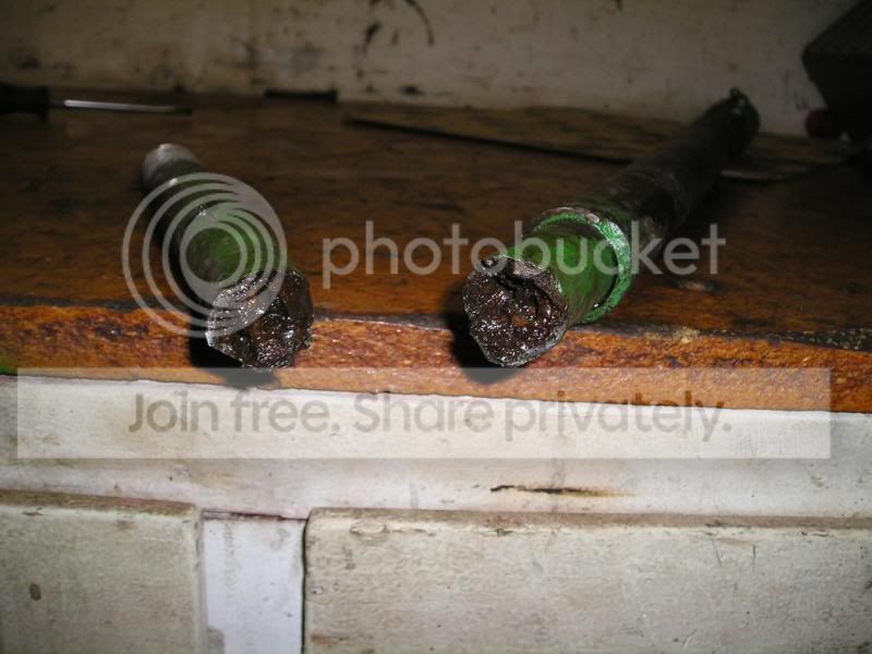
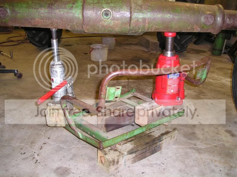
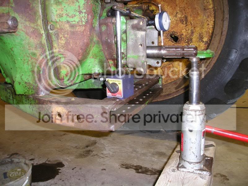
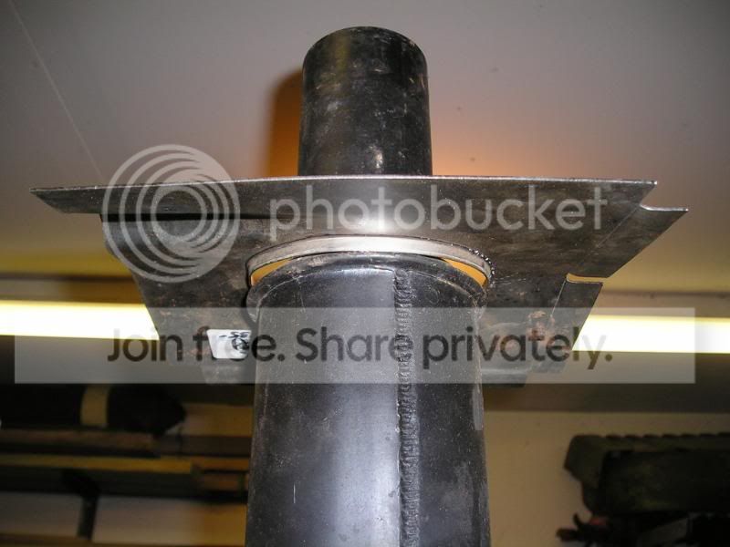
We had about 0.015” of vertical movement of the axles at the axle housings. Here we are tightening the axle nuts to put some preload on the axle bearings. Our IT manual (slightly better than having no manual) said they should have 0.0001-0.004” of end play. That did not seam right to Dad for a slow moving load bearing shaft. So he looked it up in the John Deere tech manual at the dealership. That said to have a preload. It did not give a torque but said to tighten with a 20” wrench (I think it was). So we tightened them up. They still sounded good when we spun the wheels, so we left them at that.
 
My B

P1010075CBsBAssemblyPowertrolBlaine.jpg

We put a new seal on the powertrol rockshaft piston since we had it off.

P1010076CBsBAssemblyPowertrolBlaine.jpg

Here I am putting the piston housing back on.

P1010077CBsBAssemblyPowertrolBlaine.jpg

We disassembled and inspected the powertrol pump. It had not been used for many years and was pretty much out of oil, so we were afraid the pump may have been damaged. Luckily the pump only turns when the PTO is on and looked good. We replaced a bearing and put in new seals on both ends.
 
My B

P1010012CBsBAssemblyFrontAxle.jpg

When we got the tractor, the front axle had these two steering arms. We found many places that sold the top style. But then would have had to buy 2 of them so they would match. After a couple of hours of searching the internet we found a company that sold the bottom style which matched the good one we had. We also had to replace one of the front rims that was bent and wobbled.

P1010067CBsBDisassemblyTieRod.jpg

One of the tie rods had been welded and was kind of crooked. Biewers had a new one on the shelf, so we decided to replace it. When we were trying to remove the old shaft from the tube the weld broke. This is what it looked like. Not Good. Not much was still holding. I am glad I was not driving the tractor on the road next to a river bank with this tie rod on.

P1010006CBsBAssemblyFanShaft.jpg

We went through the fan shaft and ventilation pump. We had a broken spring on the pump vane. We had to replace the bearings and also put in new seals and orings.

P1010008CBsBAssemblyChassis.jpg

Here it is going back together.
 
My B

P1010017CBsBAssemblyReductionCover.jpg

The bearing bore was worn for the first reduction gear. We measured the bore and the new bearing and wrapped shim stock around the bearing to take up the clearance and get a snug fit.

P1010019CBsBAssemblyEngineBlaine.jpg

We replaced most all external gaskets and seals. We did not want oil leaking all over our new paint job. A couple of gaskets we did not get ordered. Here Dad has shown me how to make our own gaskets. It was kind of fun.

P1010024CBsBAssemblySeat.jpg

The seat frame was warped for some unknown reason. This made it hard to slide the seat forward or back.

P1010025CBsBAssemblySeat.jpg

We rigged up this slightly dangerous looking setup under the front axle to straighten the seat frame. We tried to stay clear of where a jack could have squirted out at us. We had to flex it way beyond straight before we got it stay fairly straight.
 
Blaine,

You and your crew are doing an excellent job of restoring the family B. Your pictures and explanations in this thread are top notch. Thanks for all the good work!

If you want to belt the B up to a Prony Brake at Rollag and give it some gentle break-in time, come and see me. We can give the tractor a light load for a while, then we can vary the load up and down. We can stop any time you would like to check things out and/or make adjustments.

Later,
Jerry Christiansen
 
pony brake

Jerry,
Thanks for the invite. I will try to get down there if we aren't to busy threshing.
 
My B

More pictures

P1010027CBsBAssemblyCarburator.jpg

We got a carburetor kit from Marks Carburetor and Magneto Service.

P1010031CBsBAssemblyBrakes.jpg

We went through the brakes. The right brake was worn really bad. The pedal shaft was real loose in the bore and the pedal flopped around a lot. My uncle Bradley says that is because they used it mow hay and were always making RH turns. The LH brake pedal had been broken and was welded. We found a good left hand brake assembly at Biewers. All of the parts are the same between the left and right except the pedal. So we then had everything we needed to get both brakes fixed up. Just a set of linings and rivets from John Deere is about $100. So with the used brake assembly we did not need to by them.

P1010032CBsBTestDrive.jpg

After all of that work it was finally time to get it running again and do some test and tune. Dad rigged up a fitting in the bottom of a oil jug to use as a gas tank. He then just tie strapped it to the air cleaner. After rebuilding the carburetor, it still did not idle without having the choke pulled out. So it was back in the shop.
 
My B

P1010036CBsBAssemblyCarburatorBlain.jpg

We thought the old bushings and throttle shaft were in pretty good shape and after watching the shaft move during our test drive we decided to replace the bushings and shaft since we already had them. Here I am driving in a new throttle shaft bushing.

P1010040CBsBAssemblyCarburator.jpg

The brass part in the center is the main nozzle stem. Since we did not have the correct puller to get it out when we had it apart the first time, we left it in and cleaned what we could with the blow gun and carb cleaner.

P1010041CBsBAssemblyCarburator.jpg

Since it did not idle we needed to remove the stem to see if our problem was there. We rigged this up to remove the stem. We used a piece of ½” keystock and sockets to support it. The keystock provided a flat surface to contact the nozzle. Tapping on the top pushed it right out.

P1010044CBsBAssemblyCarburator.jpg

Dad made a copy of the idle circuit page from the John Deere tech manual at the dealership. He says if you know how it works, you can fix it. After seeing where all of the passages go, we blew air in the holes and checked to make sure air came out all of the holes that the passages led to. It turns out the small passage was plugged that goes between the arrows that are labeled “AIR FUEL MIXTURE” and “IDLE ADJUSTING NEEDLE SEAT”. We had to remove a plug and use a drill bit to clear it. That was our problem.
 
My B

P1010042CBsBAssemblyDifferentialSha.jpg

Their was only 5 gaskets on the whole tractor that we did not replace. During our test run wouldn’t you know 2 of them started to leak. The differential shaft bearing quills. We had snugged up the bolts when we had it apart the first time. This must have disturbed them enough that the started to leak. So we had to remove the clutch, first reduction cover and gears and the brake housings to get at them to replace them.

P1010043CBsBAssemblyDifferentialSha.jpg

We had to measure the old gaskets and find gasket material that was about the right thickness. We made new ones and installed. We then used a dial indicator to verify the differential shaft had the correct end play.

P1010046CBsBAssemblyPTOShaft.jpg

During our test drive we were testing the powertrol system since we had it apart. The powertrol worked fine. But wouldn’t you know we found out the PTO shaft was bent pretty bad. Bummer since we had already had it out and laying on the bench once. So we rigged up another slightly dangerous looking setup to attempt to straighten the shaft. Watching the dial indicator we would jack it up and flex the shaft a little farther each time and then spin it to see it had any effect. We finally go to the point that the whole back end of the tractor was off the ground by lifting at this point on the PTO shaft. Wow, what did it take to bend it in the first place. We had to assist the tractor weight by hitting the top of the shaft with a brass punch and a sledge hammer. We got it straight to within 10-15 thousandths at the end. You have to look at it pretty close to see that it is bent now when it is turning.
 
My B

P1010048CBsBTestDriveBlaine.jpg

With one round of rework done it was time for more test and tune. We still had a leak on the oil filter cover, even after replacing the brass washer between the bolt and the cover. We found that tapping on the bolt with a hammer seats the brass washer to the surface of the cover and that took care of the leak. We did not want to tighten the oil filter cover too tight as that will warp the metal filter can on the top. This causes a leak and low oil pressure. We know that because we had to fix that when we first got the tractor, it had almost no oil pressure on the gauge.

I put about 2-3 hours on the tractor with no more problems.

P1010049CBsBAssemblyGreaseZerksBlai.jpg


We replaced most of the grease zerks on the tractor after sandblasting so they had good check balls.

P1010051CBsBCoilProblem.jpg

After our test and tune we were feeling pretty good. We did not have any leaks and the tractor ran good. We put it away one evening and the tracter sputtered and killed. We looked and determine that our migshift gas tank had just run out of gas. The next day we noticed oil all around the governor housing. This was now one of the 3 gaskets on the tractor that we had not replaced. No sign of a leak before. This meant we now had to remove the governer housing. We decided to put some more gas in it and clean it up and make sure that is where the leak was at. Then we noticed the ignition switch got left on when the tractor ran out of gas the night before. Wouldn’t you know the points were closed and the battery was stone dead. We charged the battery. While washing it off with the hose the tractor started missing. By the time we got it back in the shop it would hardly run at all. Thinking it was wet Dad was drying the wires and noticed the coil was cracked. Turns out when we left the ignition on, the coil overheated and it leaked out all of its coil juice / oil. We installed a new 12V coil that has an internal resistor. The old one was not wired with a resistor.

Our leak was solved.


P1010053CBsBAssemblyGenerator.jpg


We went trough the generator. We had to put on some new brush holder leads and replaced the front bearing with a sealed one like the alternators have.
 
My B

P1010058CBsBPrepHood.jpg

On to the Body work. The hood had been cut like so many had to make it easy to replace the muffler.

P1010060CBsBPrepHood.jpg

Dad had heard that most of the aftermarket mufflers with the rolled flanges do not fit through the original holes in the hoods. Sure enough the patch we bought was the same way. We had to cut around the hole flange in the patch with a jig saw and bend a new flange lip on it. I am glad we found this before we had the hood painted.

P1010061CBsBPrepHood.jpg

Here is the patch after being welded into the hood. Some grinding and filler work to do yet.
 
My B

P1010063CBsBPrepSandblastingBlaine.jpg

Here I am sandblasting. We did most of the piece parts ourselves. Our air compressor is not big enough and it is a slow process. We had an old helmet in the basement. We used clear tape as tearoffs on the shield. Dad said we should get some racing tear offs you would be able to see through them better than the tape. Taped an old pair of shorts around the bottom of the helmet. Worked better than the cheap blasting hoods they have at fleet farm.

P1010066CBsBPrepGrill.jpg

We had a couple of bad areas in the grill screens. We cut some very small strips of sheet metal using tin snips. Then with a 000 tip on the torch welded them into place. Not perfect, but Will look ok from a distance.

P1010071CBsBPrepSteeringWheel.jpg

In another attempt to keep some costs down we filled in the cracks on the steering wheel with JB weld. Sanded them down level. Painted it black. Then painted with 2-3 coats of clear coat so your hands don’t get black. We will see how it holds up.

P1010072CBsBPrepSeatBack.jpg

The seat back used to have a metal back to them. Remember when you had to exchange core when you got a new seat back. We did not have one, so we made one from a piece of sheet metal. Now we will have a place to put our nice “John Deere” decal on the back of the seat.
 
My B

P1010073CBsBPrepSandblastingGuy.jpg

We hired the frame and wheels to be sandblasted. Guy Klosterman / Superior Sandblasting did it for us.

P1010075CBsBPrepSandblastingGuy.jpg

We wrapped, taped or precleaned anything we thought would be damage from sand intrusion. This saved us a lot of work and our air compressor may live to see 2009. $ well spent. He has charcoal filtered air piped into his helmet so he is breathing fresh air.

P1010078CBsBPrepSandblasting.jpg

Here is the point where it is starting to look like we are making progress. A few shots of the tractor after it was sandblasted.

P1010079CBsBPrepSandblasting.jpg


P1010080CBsBPrepSandblasting.jpg
 
My B

P1010083CBsBPaintWheels.jpg

Here it is ready for yellow paint. We are going to put on new front tires, so we will paint with the tires off. We will then mount them right on the tractor, without disturbing the lug bolt paint.

P1010085CBsBPaintWheels.jpg

2 Coats of epoxy white primer. Yellow covers better over white.

P1010086CBsBPaintWheels.jpg

Now we have a glimpse of where we are going. Shinny yellow paint. 3 coats of acrylic urethane paint. Notice the yellow fan hanging in the background. The tractor had been repainted and the fan was green. We had heard that some had yellow fans. Sure enough we found yellow paint on the fan, so yellow fan. After dad painted it, he called it his “greatest fan”.
 
My B

P1010002CBsBPaintFrame.jpg

With the wheels covered we are ready to shoot the first batch of green. Frame, radiator and half a dozen misc parts.

P1010005CBsBPaintFramePartsBlaine.jpg

Here I am shooting some primer on the radiator. Dad got a new gun for the project and is using 3Ms PPS paint cup system. It has a cup with a bladder that the paint goes in. You tip it upside down, pull the trigger to suck the air out of the top until paint comes out. Then, no more air, which means you can hold the gun at any angle you can think of and paint comes out. Since the bladder does not need to be vented, no paint dripping from a vent either. Dad says he would never paint anything with so many nooks and crannies like this, without it again.

P1010007CBsBPaintFramePrimed.jpg

Here it is with the gray epoxy primer on.

P1010009CBsBPaintFramePainted.jpg

Finally! Something Green!

P1010010CBsBPaintFramePainted.jpg

A closer view of the left side.

P1010011CBsBPaintFramePainted.jpg

And a view of the right side.

P1010013CBsBPaintAxles.jpg

The next night we masked the axle housings and the wheels to paint the axles.
 
My B

P1010014CBsBPaintAxles.jpg

Did the same on the outside of the wheels. We just had to poke a hole in the plastic and mask around the very center.

P1010019CBsBPaintedFrameAssembly.jpg

Here it is with all of the plastic off. We are ready to do some assembly!

P1010020CBsBPaintedFrameAssembly.jpg

Here I am fitting the radiator so we can cut new hoses to length.
We later mounted new tires and tubes on the front and pulled it into moms garage so we had the whole shop to work on and hang the sheet metal parts.

P1010024CBsBPaintHood.jpg


We decided to paint the inside of the hood and mount the gas tank, so we did not risk scratching the outside of the hood after it is painted.

P1010026CBsBPaintHood.jpg

Here is the hood with the gas tank installed. Dad is still doing some last minute filler work on the hood and the grill panels. He says they will not look perfect but when you are working with something like this you have to at some point say “that’s good enough”.
 
My B

P1010027CBsBPaintSheetMetalParts.jpg

Here are some shots after the final paint was put on. We screwed about twenty hooks into the ceiling. We had rows of parts.

P1010028CBsBPaintSheetMetalParts.jpg

Parts, parts. It was kind of tricky painting with out running into anything. We have ventilation fans in the corner so you had to paint so the overspray went on the parts you hadn’t painted yet.

P1010029CBsBPaintSheetMetalParts.jpg

Here is a view from the other corner of the shop. The hood did not turn out too bad, even where Dad welded in the patch around the muffler hole. But this is its good side.

P1010031CBsBPaintSheetMetalParts.jpg

Here is a view from another corner of the shop.

P1010032CBsBPaintMufflerExhaustFan.jpg

Here I just finished painting the muffler and exhaust pipe with high temp paint.
This also shows our fancy ventilation system. 2 fans bolted to a sheet of plywood. It just slips into the man door opening and blow air outside. We then tape furnace filters to the windows to somewhat filter bugs etc from the air that is sucked in.

P1010037CBsBPaintedFinalAssemblyBla.jpg


Here it is after we started the final assembly. We wrapped the muffler and air intake pipe with saran wrap to protect them from scratching while we lowered the hood down into place.
 
Super Job

I cannot believe you're sitting on your tractor with your shoes on, it looks like it needs to be stockings or booties only! You should be very proud of the job you are doing, you are paying very close attention to detail. The hardest part of doing a great restoration like you are doing, is the very first scratch. After that, they are a little easier to accept. Blaine, you are going to have a lot of fun displaying and operating this when you are completely finished. Keep up the good work! :thumb:
 
Yes Blaine, you are doing a great job documenting and presenting the process. You should be proud of your work. It is good that you are doing it right the first time and getting everything fixed on it. I look forward to seeing it in a few days. Its almost showtime.:thumb:

Darren
 
My B

P1010001CBsBWiring.jpg

We rewired the whole tractor and installed new gauges and a new light switch. We crimped and soldered all of the wires into the connectors.

P1010004CBsBGauges.jpg

We were told the gauges for our tractor should have white faces plates. But the gauges that were in the tractor were black. Don’t know if they were the originals or not. We had the tractor at the Tyler Plow Down on Saturday and took it to Rollag on Sunday. Most all of the other tractors of our vintage had black gauges. So it is beginning to look like we got some bad information there. These are the cheap made in India gauges. I would not recommend them. The temp gauge does not work at all. The Amp gauge bounces around with the tractor vibration like crazy. The oil pressure gauge reads way lower than the original, don’t know which one is right. We may have been better off with the originals. These were about 1/3 the price of the gauges from John Deere. But you get what you pay for.

Does any one know what color gauges we should have in a 48 B?

P1010005CBsBPaintedFinalAssembly.jpg


Here is the left side with all of the assembly done.

P1010006CBsBPaintedFinalAssembly.jpg

Here is the right side with all of the assembly done.

P1010008CBsBPaintedFinalAssembly.jpg

Here is the back with all of the assembly done. After a late night on Friday all we have left is to put on the decals.
 
Back
Top